POWER-TO-HEAT
SENSIBLE USAGE
In general the phrase Power-to-Heat is used to specifically describe the usage of electrical energy which is in excess from time to time. Energy excess occurs when the power input into the grid is exceptionally high or when the consumption of electricity is extremely low. These fluctuations known as volatility must be intercepted in order to stabilise the grid.
Transition system operators in Germany are legally obliged to maintain the grid frequency at 50 Hertz. In order to achieve this, the operators are dependent on the flexibility of peripheral providers and consumer installations. When the number of renewable energy sources increasing there will be more power surges than before. To turn down the unused power or to interrupt the production of e.g. wind turbines would be a bad solution. In order to achieve a sustainable and stable energy policy, one cannot afford to waste this valuable power potential that is produced at high performance times. The power must be transferred to storage points to ensure utilization at a later point in time.
- standard moderate product in low power range (110 kW up to 1 MW)
- individual heat and electricity storage and continuous flow heater concepts up to 20 MW
- free heat energy
- quick pay-off time of the installation
- heat provision despite the feed-in circuit
- emergency aggregate for heat production
- gradual, optionally also continuous circuit
- on demand introduction to marketing partners
- independent marketing partner in grid frequency regulation
- optional ready to use installation
This is where Power-to-Heat comes into play. The conversion of Power-to-Heat will allow electrical energy to be further utilised in the power grid, which is reasonable and sustainable. As part of the energy transition process, alternative methods such as Power-to-Heat will become indispensable. And as the transition system operators in Germany are dependent on flexible decentralised power plants and consumer installations, the provision of reserves will be rewarded with attractive premiums. Consequently, the investment in a Power-to-Heat installation will pay off in a very short time.

VARIATIONS
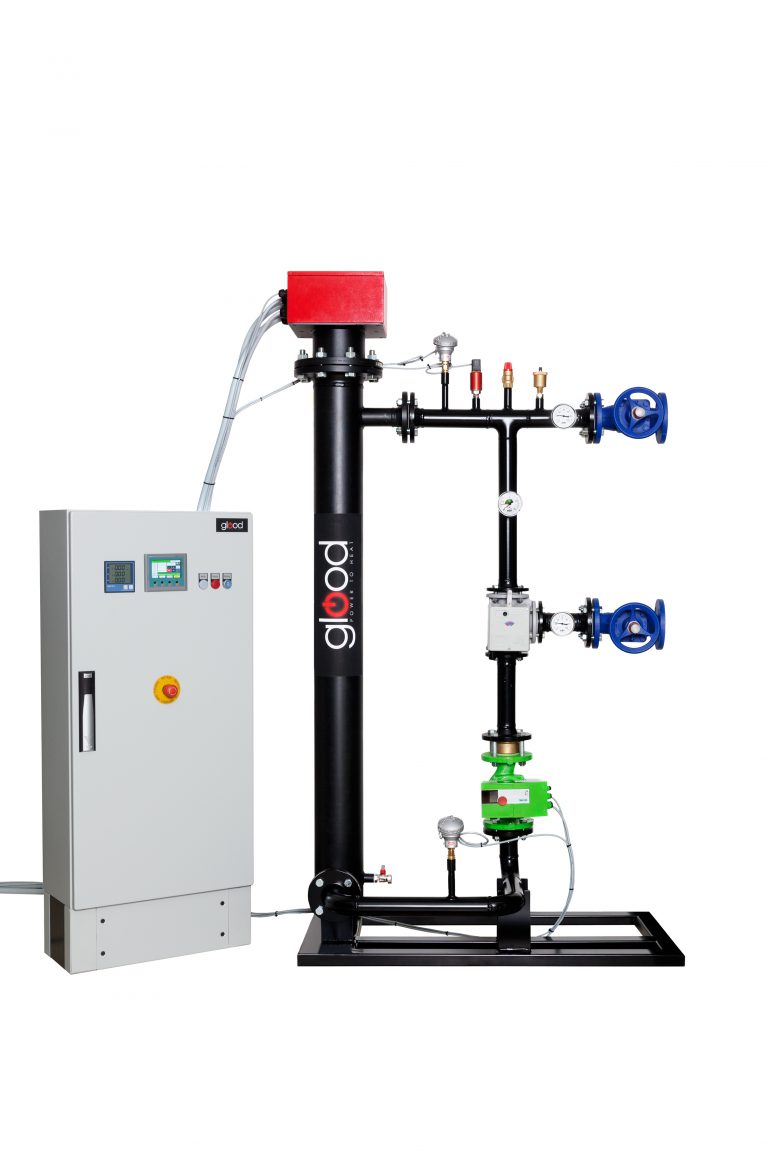
GLOOD-POWER-TO-HEAT
The Power-to-Heat module, consisting of switch boxes and electric flange radiators, is made from high quality steel and comes in two different versions.
For integration into an existing system it is recommended to install a Power-to-Heat system with a continuous flow heater. Alternatively, in newly planned systems an electric heat accumulator with integrated flange radiator would be a good solution.
Based on our experience, we would recommend to select a Power-to-Heat system with a continuous flow heater if the performance range is below 1 MW.
At higher performance levels the most suitable version has to be decided individually on a case by case basis.
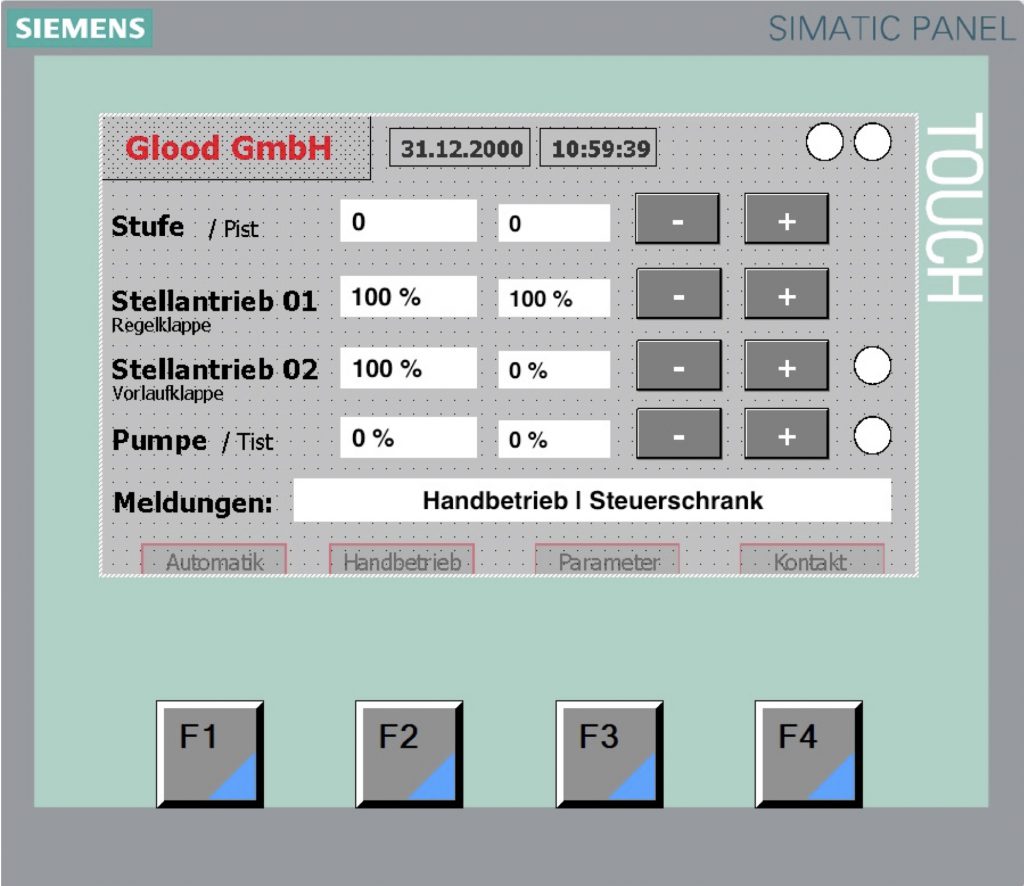
GLOOD-TOUCH-PANEL
SPS
- performance input (kW)
- flow temperature (°C)
- return temperature (°C)
- actual heating performance (kW) and the whole procedure of heat measuring meter (kW)
- volume of current indicator (m2/h)
The following parts of the Glood installation are permanently supervised, safeguarded, and monitored. In case of disturbances the error indicator module activates sending off a GSM, SMS or FAX message:
- emergency Exit
- the earth circuit interferences (z.B. (e.g. short-circuit of a heating element)
- monitoring the grid (recognition of an outage phase)
- safety temperature level controller (STB)
- exceeding of the accepted flow temperature
- monitoring by current guards
- malfunction of the circulation pump
- outage of a measuring point
- outage of the supervisory tele-control modem
- setpoint performance control
- protected control box IP55, steel model IP66
- switch box IP55, upon request IP66
- regulated assimilator for temperature expansion in the hydraulic system
- performance range from 400 V – 1.000 V
- admissible surrounding temperature for the control box of the Power-to-Heat module: 0 °C to 35 °C
- with additional optional control room heating: -15 °C to 35 °C
- with optional accompanying pipe heating of the Power-to-Heat module: -15 °C to 35 °C
- insulation
- small container
- acompanying tubular heating
- heat reading meter
- switch box with integrated heating
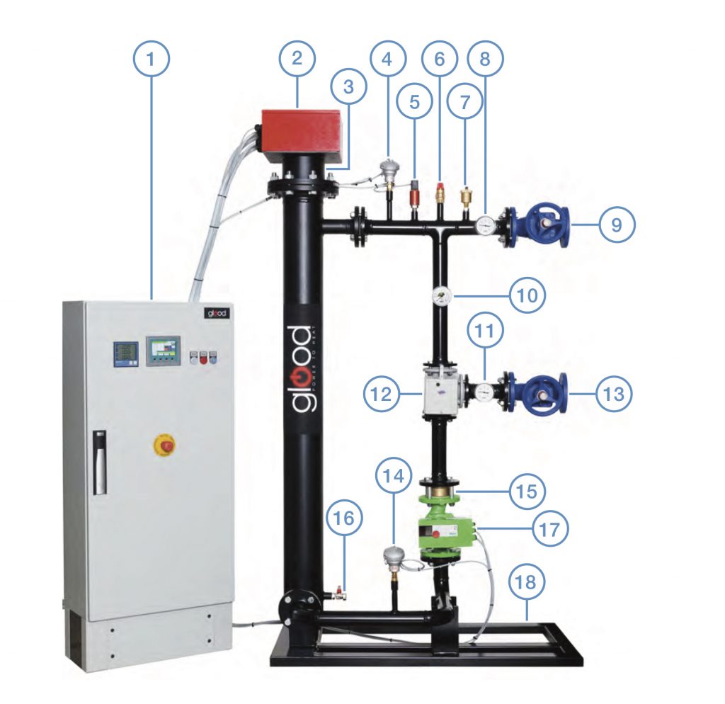
INSTALLATION MONITORING
The programmable logic controller and the Power-to-Heat module process the individual switching requirements of the providers and network operators.
This guarantees optimal heat production.
- switch box
- connection box
- electric continuous flow heater
- flow temperature sensor
- current guard
- excess pressure vent
- air ventilation
- return temperature sensor
- flow stop valve
- pressure indicator
- return temperature indicator
- three-way vent
- return stop valve
- return temperature sensor
- back pressure valve
- drain outlet tap
- inline pump
- base frame

GLOOD SWITCHBOX
MEASUREMENTS
Leistung
3 x 400 V
up to 170 kW
up to 400 kW
up to 500 kW
up to 650 kW
up to 1.000 kW
up to 2.000 kW
up to 5.000 kW
up to 10.000 kW
Leistung
3 x 690 V
up to 300 kW
up to 700 kW
up to 900 kW
up to 1200 kW
up to 1.800 kW
up to 3.600 kW
up to 9.000 kW
up to 18.000 kW
Nennstrom
400 V | 600 V
250 A | 250 A
580 A | 585 A
725 A | 750 A
950 A | 1.000 A
1.450 A | 1.500 A
2.900 A | 3.000 A
7.250 A | 7.500 A
14.500 A | 15.000 A
Maße
Breite x Höhe x Tiefe
800 x 2.000 x 400 mm
1.000 x 2.000 x 400 mm
1.200 x 2.000 x 400 mm
1.800 x 2.000 x 400 mm
2.000 x 2.000 x 400 mm
4.000 x 2.000 x 400 mm
10.000 x 2.000 x 400 mm
20.000 x 2.000 x 400 mm
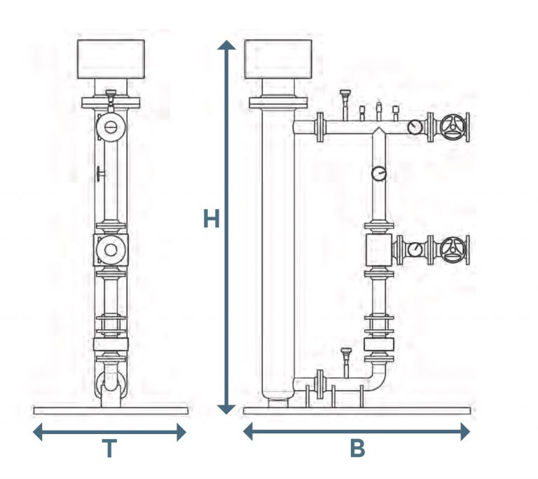
CONTINUOUS FLOW HEATER MODULE
DIMENSIONS GLOOD POWER-TO-HEAT MODULE
power
in kilowatts
up to 200 kW
up to 500 kW
up to 800 kW
up to 1.000 kW
up to 2.000 kW
up to 5.000 kW
up to 10.000 kW
dimensions
width x height x depth
900 x 2.000 x 500 mm
1.000 x 2.300 x 500 mm
1.100 x 2.600 x 600 mm
1.500 x 2.800 x 900 mm
1.500 x 2.800 x 1.700 mm
1.600 x 3.300 x 2.500 mm
1.600 x 3.300 x 5.000 mm
ELECTRIC HEAT ACCUMULATOR
DIMENSIONS GLOOD POWER-TO-HEAT MODULE
The heating net will produce more heat than is needed because of the removal of the control reserve. The size of the electric heat accumulator with integrated flange radiators will depend on the heating network storage capacity and the consumers’ behaviour. The bigger the heating storage capacity and the more constant the heat consumption, the smaller the dimensions the heat accumulator can be. If the heat storage capacity is sufficient, it is recommended to use the Power-to-Heat module with continuous flow.

power
in megawatts
up to 1 MW
up to 2 MW
up to 5 MW
up to 10 MW
diameter
in meters
2,0 m
2,0 m
2,7 m
3,0 m
height
in meters
3,1 m
4,7 m
5,1 m
7,0 m
volume
in liters
10.000 l
15.000 l
30.000 l
50.000 l
HYDRAULIC AND ELECTRIC PLAN
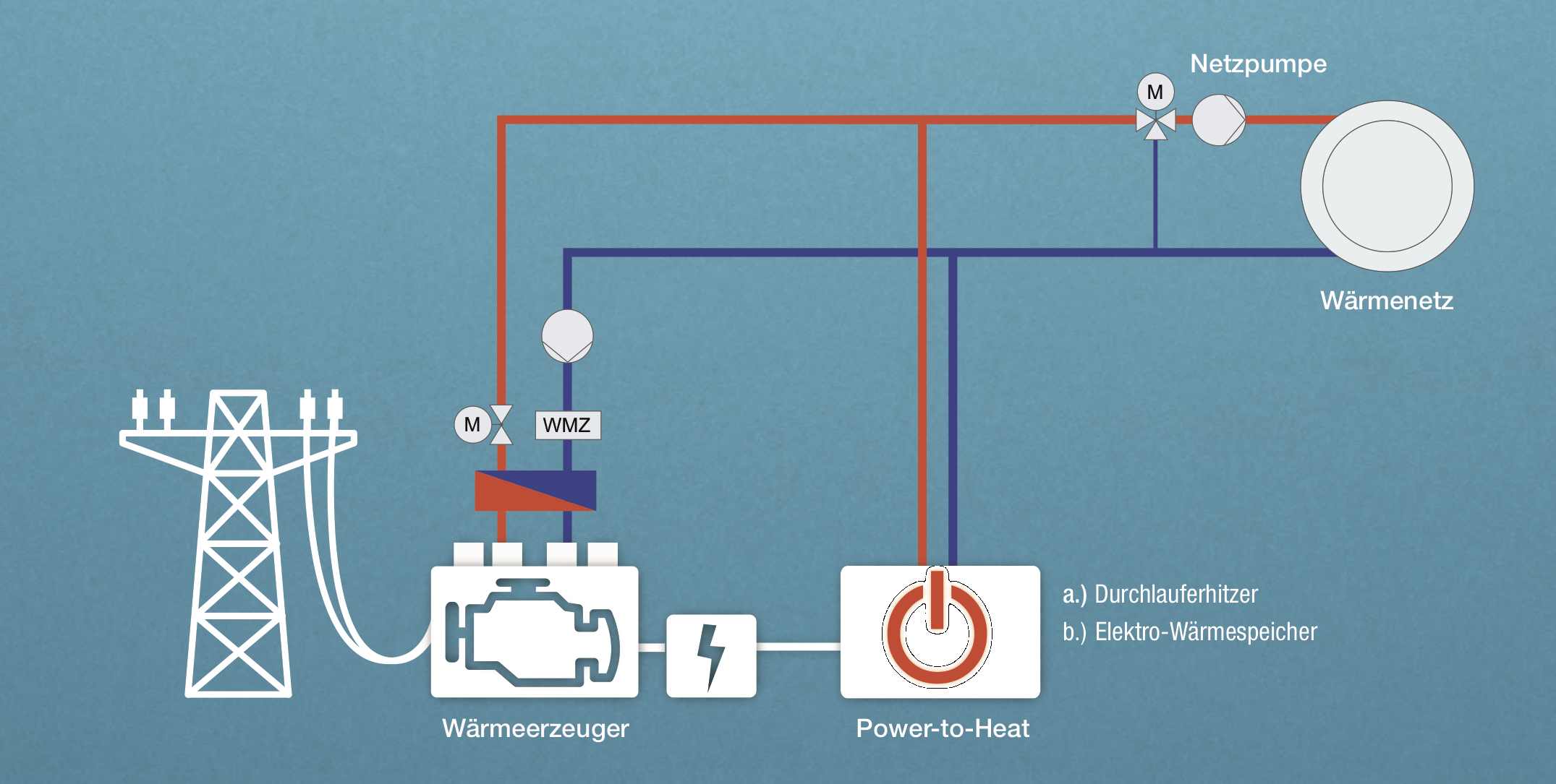
CONTROL RESERVE DEPLOYMENT
During the control reserve deployment the electricity for operation of the Power-to-Heat installations will come from either the CHP plans based on the principle of its own electricity consumption or from the national grid.
During the control reserve deployment the control in-line pump will transport the return water through the Power-to-Heat module. In this way the return water is heated to the temperature level of the flow water. Sensors monitor the temperature, pressure, and the flow speed to ensure safe operation of the installation.
The programmable logic controller controls the Power-to-Heat according to the requirements of electricity providers and network operators.
FEED-IN CIRCUIT
In feed-in circuit the regulation signal of the grid operator will be intercepted and processed by the programmable logic controller. The controller regulates the electricity production of a combined heat and power module as well as collection of electricity by the Power-to-Heat installation according to the requirements of the grid operator. This guarantees optimal heat provision and the highest accepted reduction of a CHP module.
EMERGENCY AGGREGATE
In a scenario of an outage in heat production, the Power-to-Heat installation can be used as an emergency aggregate. The programmable logic controller regulates the minimal heat provision required, taking into consideration the costs of energy retrieval from the national grid.